Oscilloscope Probe Setup
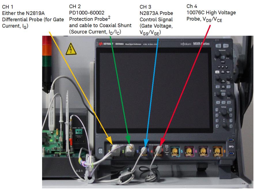
The remaining four channels are unused.
| Oscilloscope Channel1 |
Color | Oscilloscope Probe | Used to Measure | Connects to Test Module |
| 1 | Yellow | N2819A Differential Probe | Gate Current, IG | Gate Driver Module |
| Standard N2873A Probe | Clamp voltage, VCLAMP | Clamp Module | ||
| 2 | Green | PD1000-60002 Protection Probe and cable to Coaxial Shunt2 |
Source Current, ID/IC | Coaxial Shunt on DUT Module |
| 3 | Blue | Standard N2873A Probe | Gate Voltage, VGS/VGE | Gate Driver Module |
| 4 | Red | High Voltage 10076C Probe | Drain/Collector Voltage, VDS/VCE | DUT Module |
Only one of these two probes should be used in a DPT test. The N2819A Differential Probe is used when measuring Gate Current and Gate Charge. The standard N2873A probe is used with the Clamp Test Module to measure VCLAMP.
Use the 0.56 N-m (5 lb-in) 5/16 in. SMA Break-over torque wrench (provided with the PD1500A system) to tighten the SMA cable connector to the PD1000-60002 Protection Probe. Failure to do so might cause extensive ringing in the DPT measurements.
i.e., Channel 1/IG or VCLAMP is yellow, Channel 2/IDS is green, Channel 3/VGS is blue, and Channel 4/VDS is red.
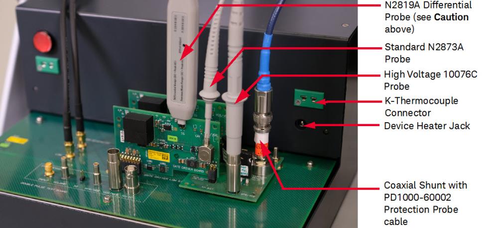
Connect Probes to the Double-Pulse Test Modules
Refer to figure below. Oscilloscope probes connect to the Test Fixture Modules as follows:
- The DUT Module uses the following oscilloscope probes:
- BNC to SMA cable from the Coaxial Shunt Resistor (ID/IC) to the PD1000-60002 Oscilloscope Protection Probe.
- 10076A High Voltage, 100:1 Probe to the VDS/VCE probe socket.
- The Low Side Gate Driver Module has two oscilloscope probe connections (see figure below):
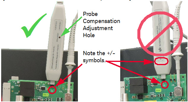
- N2819A Differential Probe connects to the IG probe socket terminals
- N2873A 10:1 Probe connects to the VGS/VCE probe socket
- Optionally, if the Clamp Circuit Test Module is used:
- Do not install the N2819A Differential Probe on the IG probe socket terminals of the Low Side Gate Driver Module.
- Attach N2873A 10:1 probe to the VCLAMP socket on the Clamp Module.
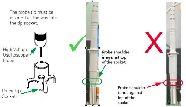
Connect the 10076C High Voltage Probe
Take extra care when inserting the 10076C High Voltage Probe in the probe socket on the DUT module or in the Deskew socket. While it is not difficult, you must ensure the probe tip is fully inserted in the socket center pin.
When inserting the 10076C High Voltage probe into the socket on the DUT module or the Deskew socket, make certain that the probe tip goes into the socket center pin. The shoulder of the probe should rest against the top of the socket.
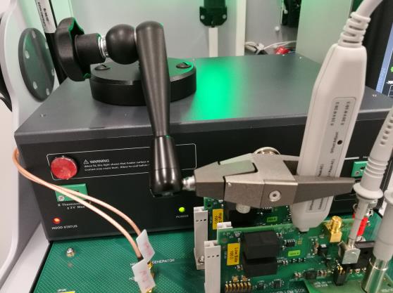
Using the N2787A 3D Probe Positioner
The N2787A Probe Positioner was included to hold the N2819A Differential Probe in place.
- Place the positioner base of the N2787A on top of the Test Fixture.
- Tighten the jaws around the N2819A Differential Probe.
- Move the probe into place on the IG pins of the Gate Drive Module.
- Tighten the Central Positioning Knob of the Probe Positioner.